
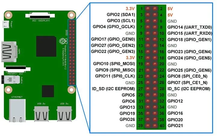
Raspberry Pi GPIO pins let a Python program read switches and sensors or control LEDs, relays and other hardware. The 40-pin header also exposes power, ground and dedicated interfaces such as I²C, SPI and UART. This guide explains how to read the header safely and choose a pin for a project.
For the complete interactive diagram, keep the Raspberry Pi GPIO Pinout reference open while you wire. Pinout.xyz distinguishes the physical position on the header from the BCM GPIO number used by many Python libraries.
The three kinds of pins
Every header position belongs to one of three practical groups:
- GPIO: General-purpose input/output pins that software can configure as digital inputs or outputs. The BCM number is the GPIO identifier, such as GPIO17.
- Power: 3.3V and 5V pins provide a supply rail. They are not ordinary GPIO outputs and must not be driven by software.
- Ground: Ground pins complete the circuit. Connect the device ground to a Pi ground pin before testing signals.
BCM numbers versus physical pin numbers
A physical pin number describes a position on the header: physical pin 11 is the eleventh header position. A BCM number describes the SoC signal assigned to that position: physical pin 11 carries GPIO17. These names are not interchangeable. A wiring diagram may say “pin 11” while Python code expects GPIO17 or 17.
Orient the Pi with the HDMI connectors on the left and the GPIO header on the right. In that view, physical pin 1 is at the top; the square pad on the underside identifies pin 1 on an unmounted board. Always compare the board orientation with the interactive pinout before inserting a jumper wire.
A practical 40-pin reference
| Physical pin | BCM / function | Typical use |
|---|---|---|
| 1 | 3.3V power | 3.3V supply rail |
| 2 | 5V power | 5V supply rail |
| 3 | GPIO2 / I²C SDA | I²C data |
| 5 | GPIO3 / I²C SCL | I²C clock |
| 6 | Ground | Circuit return |
| 7 | GPIO4 | Digital input/output |
| 8 | GPIO14 / UART TX | Serial transmit |
| 10 | GPIO15 / UART RX | Serial receive |
| 11 | GPIO17 | General-purpose input/output |
| 12 | GPIO18 / PCM CLK | Digital I/O or audio clock |
| 13 | GPIO27 | General-purpose input/output |
| 15 | GPIO22 | General-purpose input/output |
| 16 | GPIO23 | General-purpose input/output |
| 18 | GPIO24 | General-purpose input/output |
| 19 | GPIO10 / SPI MOSI | SPI controller output |
| 21 | GPIO9 / SPI MISO | SPI controller input |
| 23 | GPIO11 / SPI SCLK | SPI clock |
| 24 | GPIO8 / SPI CE0 | SPI chip select |
| 26 | GPIO7 / SPI CE1 | Second SPI chip select |
| 29 | GPIO5 | General-purpose input/output |
| 31 | GPIO6 | General-purpose input/output |
| 32 | GPIO12 / PWM0 | Hardware PWM option |
| 33 | GPIO13 / PWM1 | Hardware PWM option |
| 35 | GPIO19 / PCM FS | Digital I/O or audio frame sync |
| 36 | GPIO16 | General-purpose input/output |
| 37 | GPIO26 | General-purpose input/output |
| 38 | GPIO20 / PCM DIN | Digital I/O or audio input |
| 40 | GPIO21 / PCM DOUT | Digital I/O or audio output |
This is a working-project reference, not a replacement for the board-specific documentation. Physical pins 27 and 28 carry the ID EEPROM signals (GPIO0 and GPIO1), and the remaining header positions are power or ground. Check the complete diagram before using a less common alternate function.
Common GPIO interfaces
| Interface | Common pins | What it is for |
|---|---|---|
| I²C | GPIO2 (SDA), GPIO3 (SCL) | Multiple addressed sensors and display modules on two signal wires. |
| SPI | GPIO10, GPIO9, GPIO11 plus GPIO8 or GPIO7 | Fast peripherals such as ADCs, displays and storage devices. |
| UART | GPIO14 (TX), GPIO15 (RX) | Serial consoles and GPS or other serial modules. |
| PWM | GPIO12, GPIO13 and other software-controlled pins | Brightness, motor or servo control when the hardware and library support it. |
| 1-Wire | Configured GPIO pin | Devices such as DS18B20 temperature probes on a shared data line. |
A safe first GPIO test
Use an LED with a suitable resistor, or an LED module designed for 3.3V logic. This example uses BCM GPIO17, which is physical pin 11:
from gpiozero import LED
from time import sleep

led = LED(17)  # BCM GPIO17 = physical pin 11

try:
    while True:
        led.toggle()
        sleep(1)
except KeyboardInterrupt:
led.off()Code language: Python (python)- Never connect 5V to a GPIO signal pin. Raspberry Pi GPIO uses 3.3V logic.
- Use a resistor to limit LED current, and use a level shifter or voltage divider when a peripheral outputs more than 3.3V.
- Turn the Pi off while changing wiring, and verify the pin number convention in both the guide and the code.
- Do not draw more current than the board, power supply or peripheral is designed to provide.
GPIO troubleshooting checklist
- Confirm whether the diagram uses physical, BCM or WiringPi numbering.
- Check that the circuit has a shared ground with the Pi.
- Check the pin is not already claimed by I²C, SPI, UART, a HAT or a background service.
- Check the input pull-up or pull-down setting and whether the switch is active-low.
- Return to the interactive Pinout.xyz diagram for alternate functions and the exact header orientation.
Source and next step
Pin names, physical positions, alternate interfaces and orientation in this guide are based on Pinout.xyz’s Raspberry Pi GPIO Pinout reference. Use it as the canonical visual check before wiring a project. Next, try the Raspberry Pi weather dashboard project and map its sensor wires to the GPIO numbers in the code.